Background
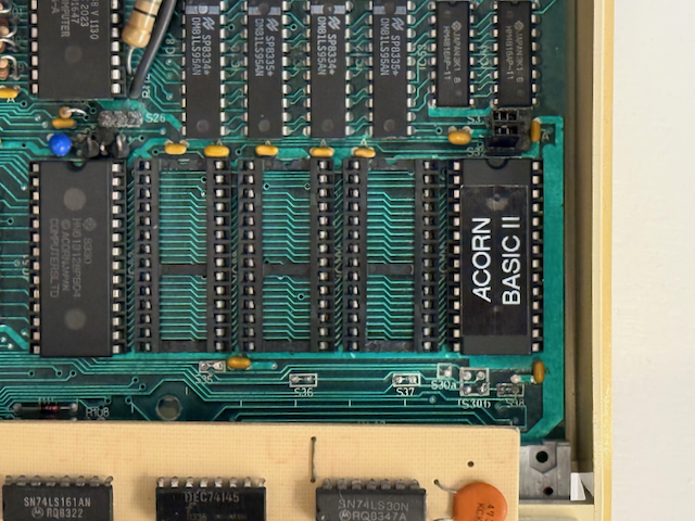
While installing an IFEL Sideways RAM/ROM Board (PDF) in one of my Beebs I ran into a hardware issue. The BASIC and MMFS ROMs were installed in the rightmost sockets on the mainboard as a “fallback” option. After completing the installation, the Beeb would no longer start at all. No video, nothing. Time to start troubleshooting!
Troubleshooting steps
Return to minimal configuration
First step is to return the machine to a minimal configuration and see if it starts working again.
Suspecting an issue with the installation of the IFEL board, I first checked all connections and jumper settings in the machine. No progress, so I removed it. Still no joy. Next I removed all Sideways ROMs from the mainboard. With only the OS ROM installed, it started with a familiar “Language?” prompt. Good.
Locate the source of the problem
After confirming that the machine works in minimal configuration, I put the BASIC ROM in socket IC101 - still fine. Moved it to IC100, and the machine went dead again. With BASIC in sockets IC52 or IC88 the machine worked fine too. So the issue is specific to having a ROM installed in IC100.

Passive checks: continuity test
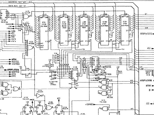
Time to look at the schematic. All ROM sockets are wired in parallel, except for pins 1 (Vpp on an EPROM) and 20 (/E, output enable, active low). With my multimeter in continuity setting I checked all pins on the ROM sockets - fine, so the socket itself did not appear to be broken. I traced connections from IC101 pin 20 back all the way to IC20 pin 10 - all continuity checks passed.

Note that defective or corroded IC sockets are a common cause of problems - but apparently not this time. So we need to proceed to the next step: checking the logic signals on the “live” machine.
Active checks: logic signals
For this step you’ll want to use a logic probe or oscilloscope. A multimeter is less suitable for checking logic signals but it might work. I used my battery-powered portable oscilloscope (Owon HDS2102S) to completely avoid ground loops.
With TTL devices, 0.0V - 0.8V is considered “Low”, 2.0V - 5.0V is considered “High”. Values between 0.8V and 2.0V yield undefined results.
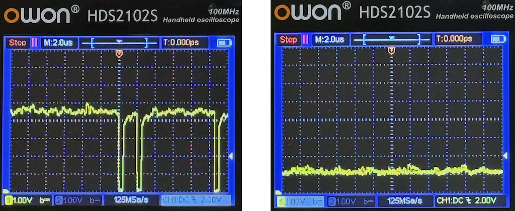
I measured the outputs on IC20 without any ROMs installed. The oscilloscope trace on the left shows IC20 pin 9 (IC101) behaving as expected: mostly High, with brief Low pulses when the ROM socket is being accessed. The oscilloscope trace on the right shows the signal on IC20 pin 10 (IC100).

The output of IC20 pin 10 is stuck at around 1V, which is usually interpreted as “Low” - any ROM in IC100 will always be Enabled, corrupting signals on the data bus. This explains why the system is completely dead whenever a ROM is installed in IC100 - the CPU, video controller and other ROMs cannot properly access the data bus.
Repair
IC20, a 74LS139 dual 2-to-4 decoder (datasheet PDF), is defective and needs to be replaced. I carefully cut each pin of the IC, desoldered everything and installed an IC socket. After inserting a new 74LS139, the Beeb was 100% OK again.
Thanks to the wonderful people at StarDot and BigBenClub for their help and suggestions!