David Martin, a.k.a. ‘3ATIVE VFX Studio’ on Youtube, posted a great tutorial video about controlling this air purifier with Home Assistant by adding an ESP8266. His code is available on Github. I’ve mostly followed his tutorial, except for freeing up the ESP8266 pins related to I2C.
I started by modifying the original IKEA circuit board:
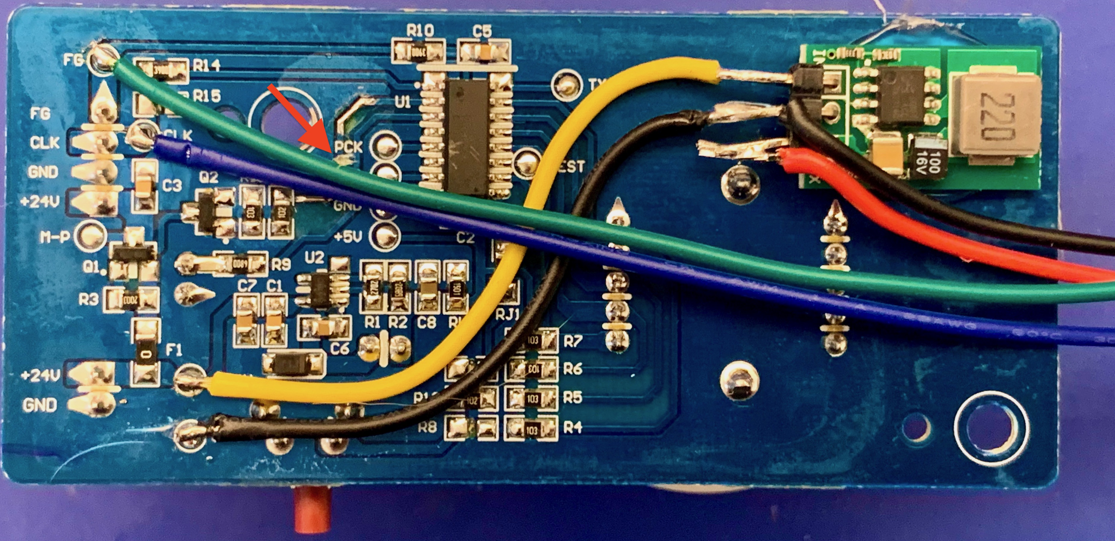
In the top right you can see a 5V voltage regulator, based on the HX1314G chip. This module is pin-compatible with an LM7805 and can handle 24V input. I hot-glued it to the standard PCB.
- Yellow (+24V) and black (GND) wires connect the 24V supply voltage to the regulator
- Red (+5V) and black (GND) wires connect to the D1 Mini ESP8266 board 5V power input pins
- Green is the fan ‘FG’ signal. It connects to GPIO12 on the ESP8266 via a 10k resistor
- Blue is the fan ‘CLK’ signal. It connects to GPIO13 on the ESP8266
- I cut the PCB trace from the top of resistor R13 to chip U1 (near the red arrow)
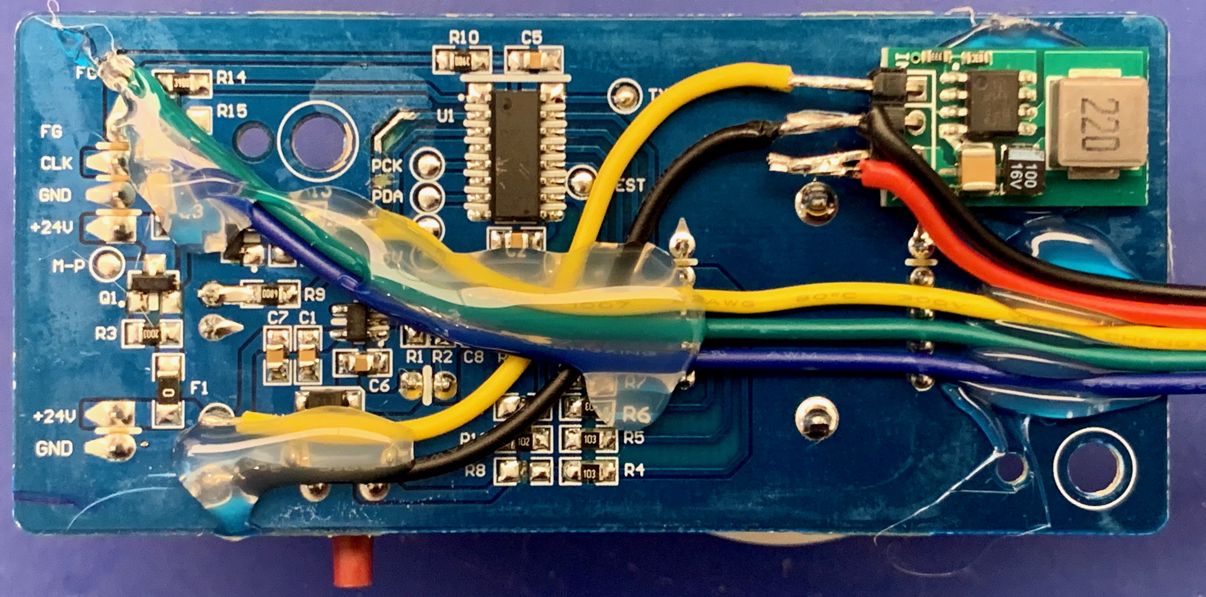
I then soldered a second yellow wire to the top of resistor R13 (‘Fan MOSFET’). It connects to GPIO14 on the ESP8266. After testing, I applied more hotglue to keep the wiring in place.
Next, I wired up the D1 Mini ESP8266 board. I wanted to add optional I2C sensors; for example, a BME680 temperature/humidity/pressure/gas sensor or an SCD40 ‘true’ CO2 sensor (not that the air purifier will change CO2 levels, but anyway).
The ESP8266 has a single I2C interface on pins GPIO4 (I2C-SDA) and GPIO5 (I2C-SCL). In David’s tutorial, D2 (GPIO4) was in use for the ‘Fan MOSFET’ signal so I moved that to D5 (GPIO14).
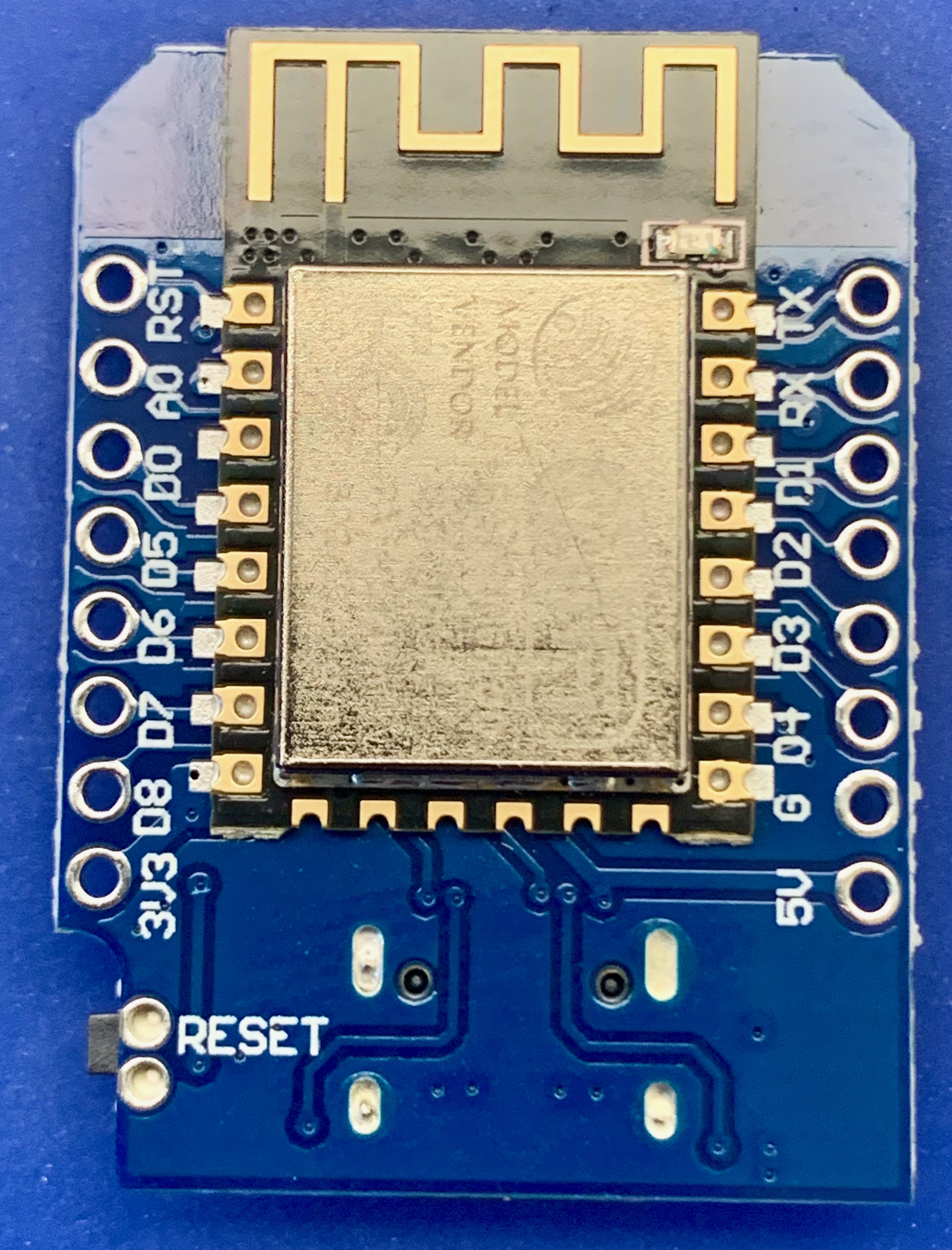
So I made the following connections:
- Red wire (+5V) to ‘5V’ pin
- Black wire (GND) to ‘G’ pin
- Green wire (‘FG’) to ‘D6’ pin (GPIO12) via a 10kOhm resistor
- Blue wire (‘CLK’) to ‘D7’ pin (GPIO13)
- Yellow wire (Fan MOSFET, top of R13) to ‘D5’ pin (GPIO14)
Multiple I2C devices can be connected as needed. They need to be connected as follows:
- I2C ‘SCL’ to ‘D1’ pin (GPIO5)
- I2C ‘SDA’ to ‘D2’ pin (GPIO4)
- Power 0V to ‘G’ pin
- Power 3V3 to ‘3V3’ pin
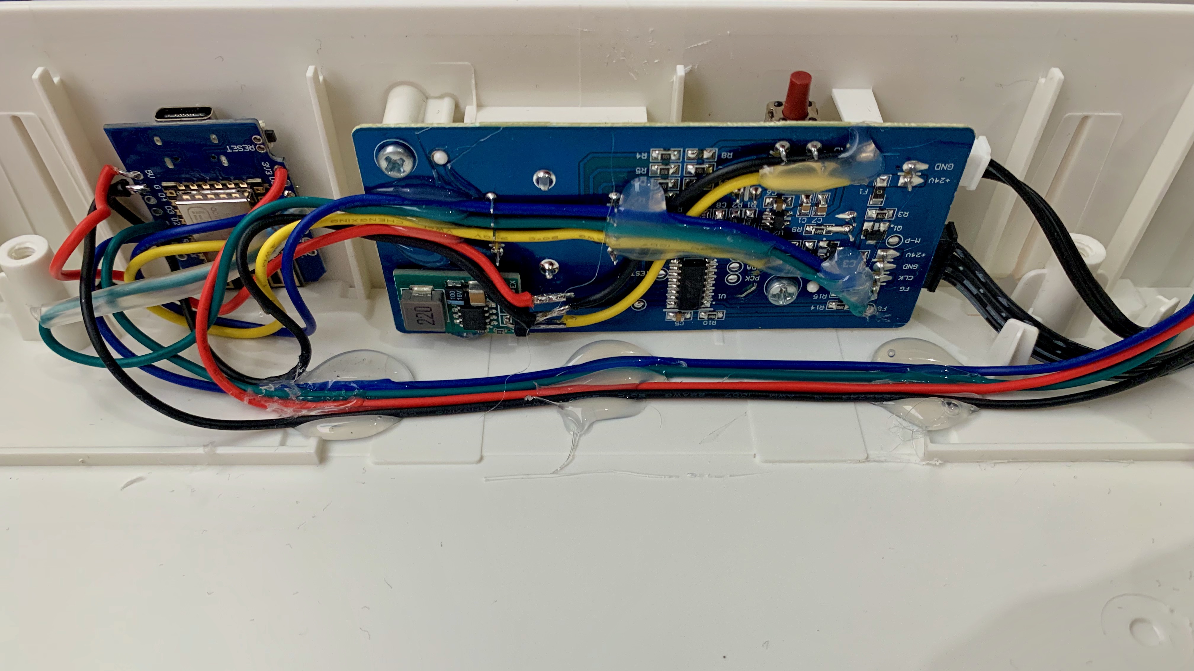
The image below shows how I hotglued the ESP8266 board to the fan housing. I had a BME680 sensor so I wired that up, drilled a small hole in the side of the fan and - you guessed it - hotglued it in place as well. The blue/green/red/black wires connect the BME680 sensor to the ESP8266 board.
Software
I started by flashing ESPHome onto the ESP8266 board. The full ESPHome configuration is as follows:
## IKEA Fornuftig upgrade with ESP8266, originally from https://github.com/3ative/ikea-air-filter
## BME680 temperature / humidity / pressure / gas sensor (Vcc = 3v3)
## ESP8266 Wemos D1 Mini pinout:
# D0  GPIO16  WAKE
# D1  GPIO5   I2C-SCL  / BME680 SCL
# D2  GPIO4   I2C-SDA  / BME680 SDA
# D3  GPIO0   FLASH
# D4  GPIO2   LED
# D5  GPIO14  SPI-SCLK / ESP8266 D5 <-> Fornuftig top of R13, remember to cut PCB trace to U1 (3ative: D2)
# D6  GPIO12  SPI-MISO / ESP8266 D6 <-> Fornuftig fan FG via 10k resistor
# D7  GPIO13  SPI-MOSI / ESP8266 D7 <-> Fornuftig fan CLK
# D8  GPIO15  SPI-CS

substitutions:
  devicename: "fornuftig-hobbyroom"
  long_devicename: "Air purifier hobbyroom"

esphome:
  name: "${devicename}"
  platform: ESP8266
  board: d1_mini
  esp8266_restore_from_flash: true
  ## Read the stored value for the "Filter Age"
  on_boot:
    - pulse_counter.set_total_pulses:
        id: filter_counter
        value: !lambda "return id(filter_age) * 100;"

preferences:
  flash_write_interval: 300s

globals:
  ## Save the Filter Age Value to Flash and restore it
  - id: filter_age
    type: int
    restore_value: yes

# ESP8266 has single I2C bus, SCL = D1/GPIO5; SDA = D2/GPIO4
i2c:
  scl: 5
  sda: 4
  scan: true

# Proprietary Bosch library for BME680 providing IAQ etc.
bme680_bsec:
  address: 0x77

wifi:
  ssid: !secret esphome_wifi_iot_ssid
  password: !secret esphome_wifi_iot_password
  ap:
    ssid: "${devicename} hotspot"
    password: !secret fornuftig_ap_password

# Fallback to Captive Portal AP in case WiFi fails to connect
captive_portal:

# web_server:
#   port: 80

api:
  ## uncomment the lines below if you wish to encrypt API traffic
  encryption:
    key: !secret esphome_api_key

ota:
## uncomment the line below if you wish to use an ota-password
# password: !secret esphome_ota_password

logger:
  level: INFO
  # Disable logging via UART
  baud_rate: 0
  logs:
    pulse_counter: none
    number: none
    sensor: none
    switch: none

binary_sensor:
  ## Sensor "Filter Dirty" for Home Assistant
  - platform: template
    name: "${long_devicename} filter dirty"
    id: filter_dirty
    icon: mdi:trash-can-outline
    publish_initial_state: true

button:
  ## Reset Button for "Filter Age"
  - platform: template
    name: "${long_devicename} filter reset"
    id: reset_button
    icon: mdi:Redo
    ## Reset the counter ##
    on_press:
      - pulse_counter.set_total_pulses:
          id: filter_counter
          value: 0
      - delay: 1s
      ## Turn of the warning LED
      - switch.turn_off: onboard_led
      - lambda: !lambda |
          id(filter_dirty).publish_state(false);
      ## Immediatly save to Flash
      - lambda: !lambda |
          global_preferences->sync();

number:
  ## Slider for Fan Speed 0-6, 0 = Off
  - platform: template
    name: "${long_devicename} fan speed"
    id: fan_speed
    icon: mdi:air-filter
    update_interval: never
    optimistic: true
    min_value: 0
    max_value: 6
    initial_value: 0
    step: 1
    set_action:
      - if:
          condition:
            ## Is the slider is 0 or above? ##
            - lambda: |-
                return x >= 1;
          then:
            ## Turn on the fan MOSFET and the "servo" ##
            - switch.turn_on: fan_mosfet
            - servo.write:
                id: fan_motor
                level: 1
            ## Change the PWN signal based in the Slider value (Multiples of 50) ##
            - output.esp8266_pwm.set_frequency:
                id: fan_pwm
                frequency: !lambda return x * 50;
          ## If not (else) turn off the MOSFET and the set PWM to 0 ##
          else:
            - switch.turn_off: fan_mosfet
            - output.esp8266_pwm.set_frequency:
                id: fan_pwm
                frequency: !lambda return 0;

sensor:
  # Uptime in seconds
  - platform: uptime
    name: "${long_devicename} uptime"
    id: uptime_seconds
    update_interval: 10s
  ## Read the pulses coming back the from the fan motor (ESP8266 D6 <-> Fornuftig fan FG via 10k resistor)
  - platform: pulse_counter
    pin: D6
    id: filter_counter
    count_mode:
      rising_edge: INCREMENT
      falling_edge: DISABLE
    update_interval: 2s
    filters:
      - multiply: 0.0001
    ## Keep a running total of how much the filter has been used
    total:
      name: "${long_devicename} filter age"
      icon: mdi:biohazard
      unit_of_measurement: Age
      filters:
        - multiply: 0.01
      on_value:
        - lambda: !lambda |
            id(filter_age) = x;
        # Turn On: On-Board LED and "Dirty" Binary Sensor
        - lambda: !lambda |
            auto timer = 3153600; // "30" for demo. Recommended 6 Months = 3153600
            if (x >= timer) {
              id(onboard_led).publish_state(true), id(filter_dirty).publish_state(true);
            }
  ## BLE680 gas/temperature/pressure/humidity sensor using proprietary library
  - platform: bme680_bsec
    temperature:
      name: "${long_devicename} temperature"
    pressure:
      name: "${long_devicename} pressure"
    humidity:
      name: "${long_devicename} humidity"
    iaq:
      name: "${long_devicename} IAQ"
      id: iaq
    co2_equivalent:
      name: "${long_devicename} CO2 equivalent"
    breath_voc_equivalent:
      name: "${long_devicename} VOC equivalent"

text_sensor:
  - platform: bme680_bsec
    iaq_accuracy:
      name: "${long_devicename} IAQ accuracy"

  - platform: template
    name: "${long_devicename} IAQ classification"
    icon: "mdi:checkbox-marked-circle-outline"
    lambda: |-
      if ( int(id(iaq).state) <= 50) {
        return {"Excellent"};
      }
      else if (int(id(iaq).state) >= 51 && int(id(iaq).state) <= 100) {
        return {"Good"};
      }
      else if (int(id(iaq).state) >= 101 && int(id(iaq).state) <= 150) {
        return {"Lightly polluted"};
      }
      else if (int(id(iaq).state) >= 151 && int(id(iaq).state) <= 200) {
        return {"Moderately polluted"};
      }
      else if (int(id(iaq).state) >= 201 && int(id(iaq).state) <= 250) {
        return {"Heavily polluted"};
      }
      else if (int(id(iaq).state) >= 251 && int(id(iaq).state) <= 350) {
        return {"Severely polluted"};
      }
      else if (int(id(iaq).state) >= 351) {
        return {"Extremely polluted"};
      }
      else {
        return {"error"};
      }

servo:
  ## Set the PWM signal to 50% Duty cycle (ESP8266 D7 <-> Fornuftig fan CLK)
  - id: fan_motor
    output: fan_pwm
    max_level: 50%

output:
  - platform: esp8266_pwm
    id: fan_pwm
    pin:
      number: D7

switch:
  ## Control the on-board Motor Power MOSFET (ESP8266 D5 <-> Fornuftig top of R13, remember to cut PCB trace to U1)
  - platform: gpio
    pin: D5
    id: fan_mosfet
    on_turn_on:
      switch.turn_on: onboard_led
    on_turn_off:
      switch.turn_off: onboard_led

  ## Filter Dirty LED
  - platform: gpio
    id: onboard_led
    pin:
      number: D4
      inverted: true
Do not forget to define the ‘!secret’ entries in ESPHome.
Conclusion
The Home Assistant integration works well. Unfortunately, the local controls (fan speed selector, ‘filter reset’ switch and ‘replace filter’ LED) no longer work. I can live with this.
If you want a nicer solution (without the hotglue), replacing the IKEA PCB with a custom PCB would be a nicer option - you could re-use the local controls, perhaps using the ‘filter reset’ switch to toggle between local and remote control.
]]>
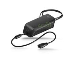 I don’t want to leave our ebike battery charger powered on all the time, so let’s have Home Assistant monitor the charging process and switch off the charger when done.