 I got some KAKU (Klik Aan Klik Uit) switches to control lighting etc. These can be remote controlled using a JeeNode with the OOK433 Plug.
This plug contains a separate receiver and transmitter board. After consulting the schematic, it appears that the receiver is hooked up to the AIO pin, while the transmitter is connected to the DIO pin. This information is needed when reconfiguring the software for the actual Port socket you plugged the OOK433 into.
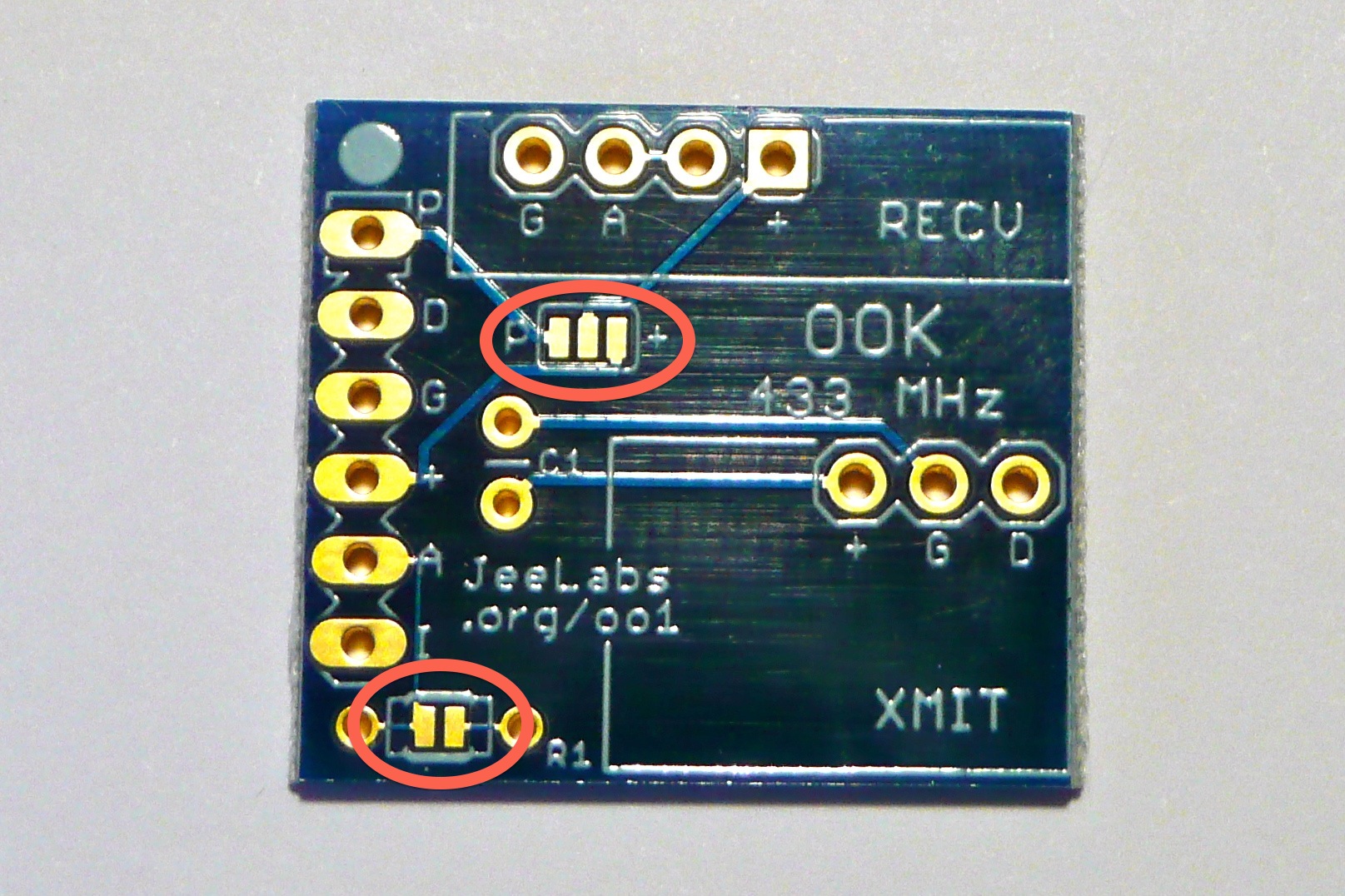
There are two solder jumpers that need to be made (marked in the picture on the right):
- The upper one selects supply voltage. According to current documentation, the rightmost two pads need to be bridged, selecting +3V.
- The lower solder jumper should always be bridged (except if a resistor R1 is to be installed)
Note that the Receiver and Transmitter modules have “+5V’ and “+12V” markings on them – apparently, they also work at this much lower voltage.
 After making these two solder jumpers, continue assembly. I soldered a 6-pin header (not included with the kit) to the Port connector so I can plug it straight into a JeeNode.
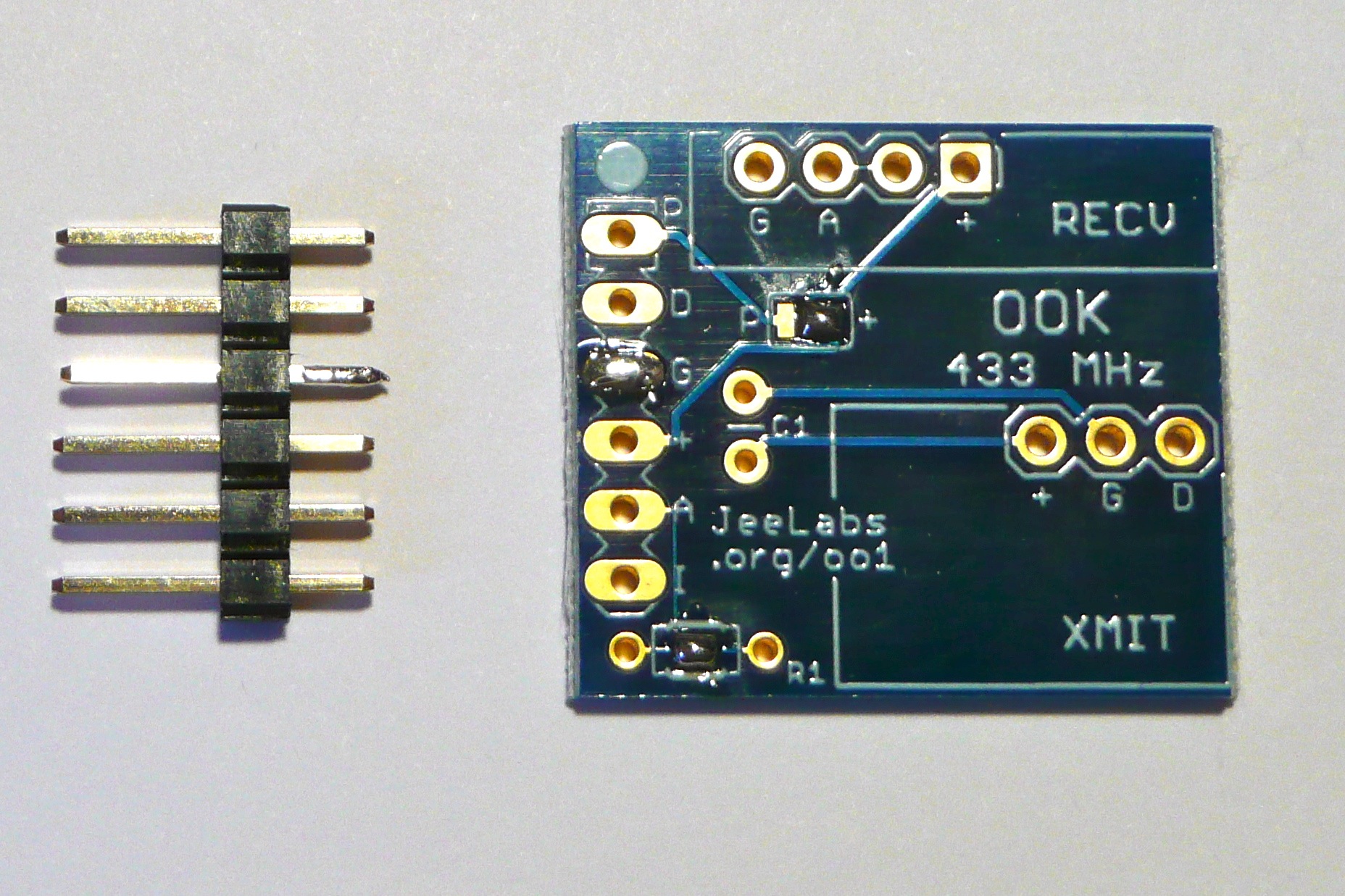
The trick here is to apply some solder to one pad and one pin first. Then, hold the header in place while re-heating the solder on that pad. The remaining pads can now be soldered properly. The picture shows the solder jumpers I made, as well as the preparations for soldering the 6-pin header in place.
Make sure you get shiny solder joints that are properly heated (lead-free solder tends to shine a bit less than the 60/40 I use).
Next up: the transmitter module. Note that when soldering, you usually work from “lowest” to “highest” component. This makes life easier. Simply insert the transmitter module into the 3 holes and solder it. Note that the module has an antenna connector (marked “ANT”) for adding a straight-wire antenna, approx. 17cm in length. This corresponds to 1/4 wavelength at 433MHz.
 Finally, the receiver module. Insert it into the 4 holes and solder it. This module also has an antenna connector, you may want to add a 17cm straight-wire antenna here as well.
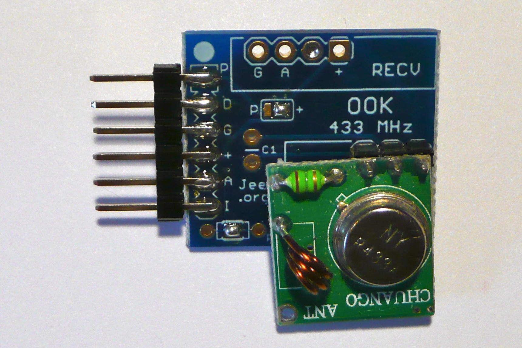
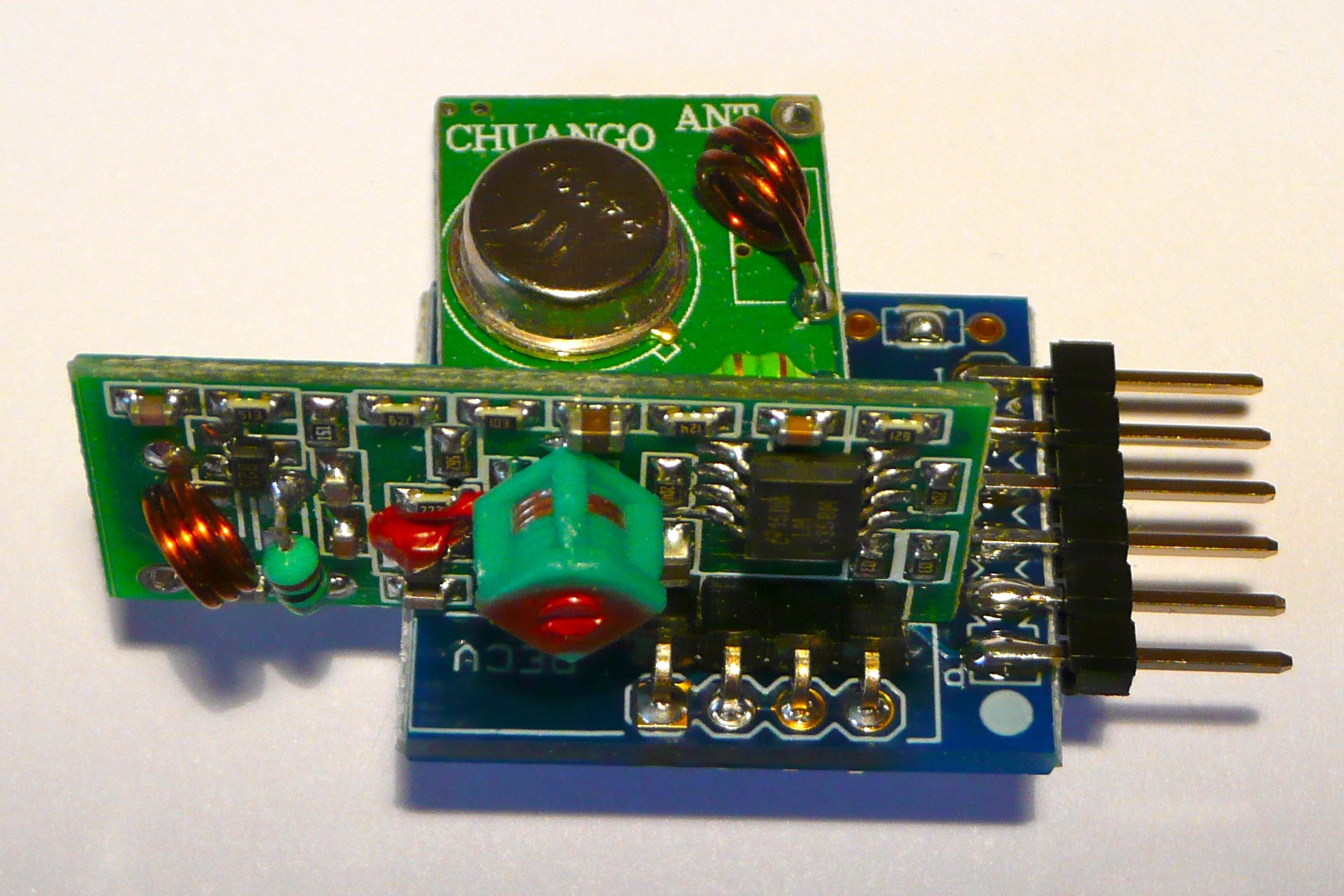
The end result is in the picture below. Now for the moment of truth: trying to make it work with a JeeNode and a software sketch.
This is where my trouble began. I used various sketches with my new KAKU remote, to no avail:
- kaku_demo
- KlikAanKlikUit_A_type
- ookRelay
- ookScope2
- recv433_test
I searched the blog and forums using Google (“site:jeelabs.org OOK433”) and found several people struggling to make the OOK433 Plug work. Several issues appear to be at play here:
-
Confusion regarding the correct supply voltage; it seems that +3V is not enough.
This means that you would need to bridge the leftmost two pads on the upper solder jumper, instead of the rightmost two pads. -
Confusion regarding port numbers / Arduino pin numbers.
The KlikAanKlikUit_A_type sketch is the only one that seems to clearly document where the Plug is expected to be for the sketch to work. -
Confusion regarding the antennas being “optional” or not.
I have no antennas connected at the moment, but I’m using the remote at close range so it should not be a problem. -
Confusion regarding the different KAKU protocols out there.
I think I have the most recent protocol, with house code (A-D on my remote). The old protocol apparently does not have that.
All in all, quite a few variables ;-)
I decided to go ahead with the ookScope2.ino sketch – that appears to be a fairly recent sketch; hopefully that code works as expected. First hurdle: determining which port to plug the OOK433 Plug into…
The code contains this line:
#define OOK_PIN 2 // this is the input pin with the signal to be analyzed
This might refer to AVR pin PD2, Arduino pin “Digital 2” but that would mean it’s connected to the RFM12B INT line! Not very likely… I tried the code, and apart from the [ookScope] identifier, nothing happened. So, where does that OOK433 Plug need to go for the sketch to work?
OK, back to the schematic I talked about at the start of this post. The OOK433 receiver module appears to be connected to the AIO pin. If I want to use the plug in Port 3, I need to find the proper value for AIO3. That would be Analog 2 / Digital 16 (hey, ‘2’ looks familiar but it didn’t work).
I then tried seting OOK_PIN to 16 (Digital 16), plugged the OOK433 into Port 3 and behold! The sketch starts, and emits binary garbage on the serial output! This is promising!
Next up: install the JeeRev / JeeMon software on my Mac according to instructions. Unfortunately, that didn’t result in a nice bar graph display – the bars remain at zero, even though I pressed the remote buttons. Perhaps the ookScope2.ino sketch doesn’t work with this version of the JeeMon software? What’s next? Debugging the JeeMon installation? Nah…
Anyway, my head hurts after reading through the various forum and blog posts – once I get this working I’ll post “part 2” of this adventure ;-)

P.S.: I think we as a community should work on improving the “Out of Box Experience” for the JeeLabs hardware. Detailed assembly instructions, a simple test sketch with clear instructions on setting up the test bed – life would be so much easier ;-) If possible, add a low-level hardware diagnostics mode in that test sketch to help isolate the cause of any hardware-related problems. For example, try communicating over the SPI / I2C bus. If that doesn’t work, you might have to inspect your soldering. And most importantly: find a way to reduce @JCW’s workload – it would not be realistic to expect him to do all the work on documentation / test sketches etc.
Still massively enjoying the JeeLabs learning experience, one (steep) step at a time ;-)
Onwards!