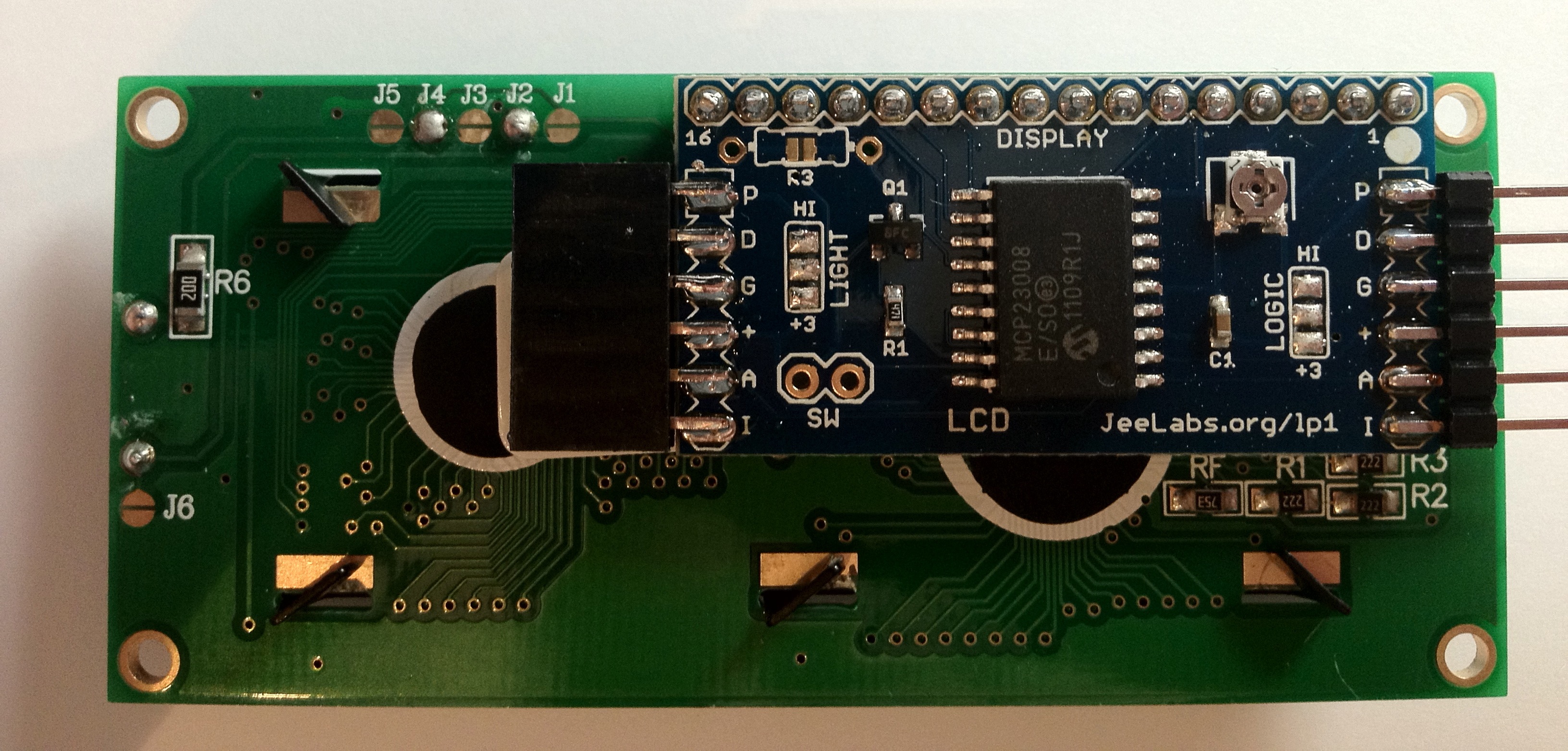
 Today I received my new items from JeeLabs – an LCD Plug and a set of stacking headers.
After soldering the control board to the LCD display,I tried compiling the lcd_demo.ino demo sketch. No luck – it seems that the code no longer compiled with Arduino 1.0.
I added the include-file that was missing:
#include <PortsLCD.h>
and suddenly… nothing happened.

I verified the connections – everything looked good. Oh well – “if all else fails, read the manual”. There were no detailed assembly instructions for this kit, so I had to search through various posts to help debug the issue.
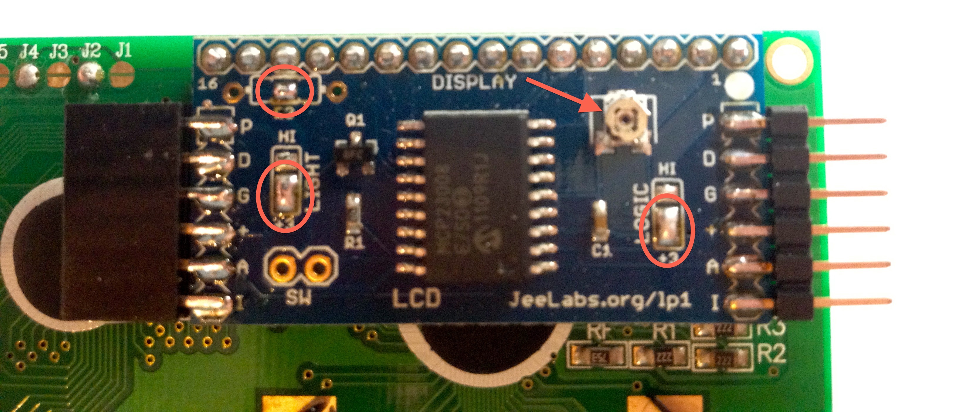
Turns out that you have to set two solder jumpers (Logic to 3v3, Backlight to 3v3) as well as short out a current limiting resistor (which is not actually present on the board). Click the annotated image on the left for a (blurry) close-up.
This still did not seem to solve the problem – the backlight worked, but still no text on the display. After adjusting the contrast level with the trimpot (near the red arrow in the image), the display finally sprang to life. I had to rotate it completely counter-clockwise.
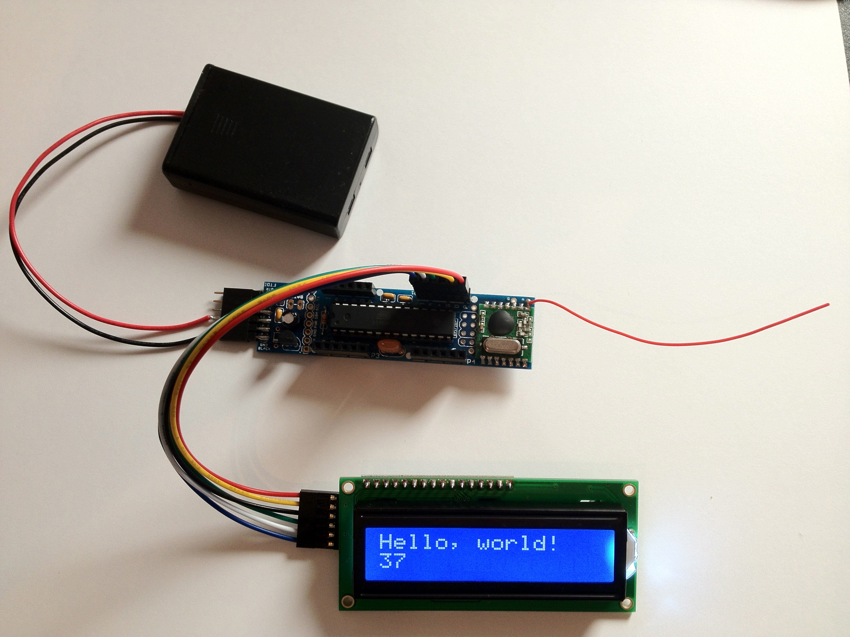
The test assembly looks like this – battery holder on top, JeeNode in the middle, LCD Plug at the bottom of the image. The LCD Plug is connected to Port 1 on the JeeNode.
